
HT16K33 16X8 Led Matrix Driver โมดูลควบคุม 7 segment แบบ 16x8 สต็อกไทยส่งไว


รายละเอียดสินค้า
FEATURES :
- 16 x 8 segment driver
- 13 x 3 matrix key scanning w/ interrupt output
- 16-level dimming
- Built-in clock and display update
- I2C interface
- 5V operation
HT16K33 Chip:
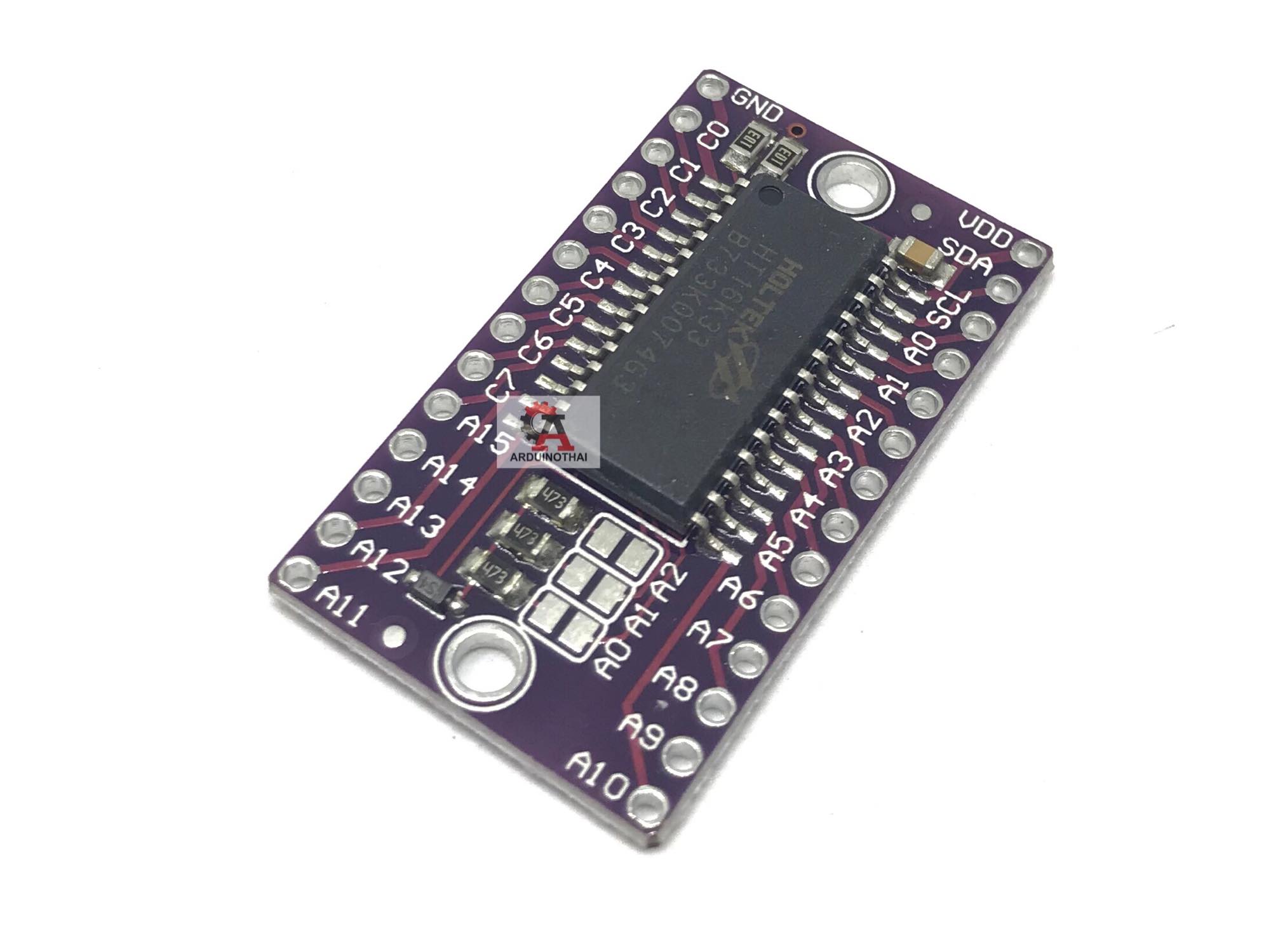
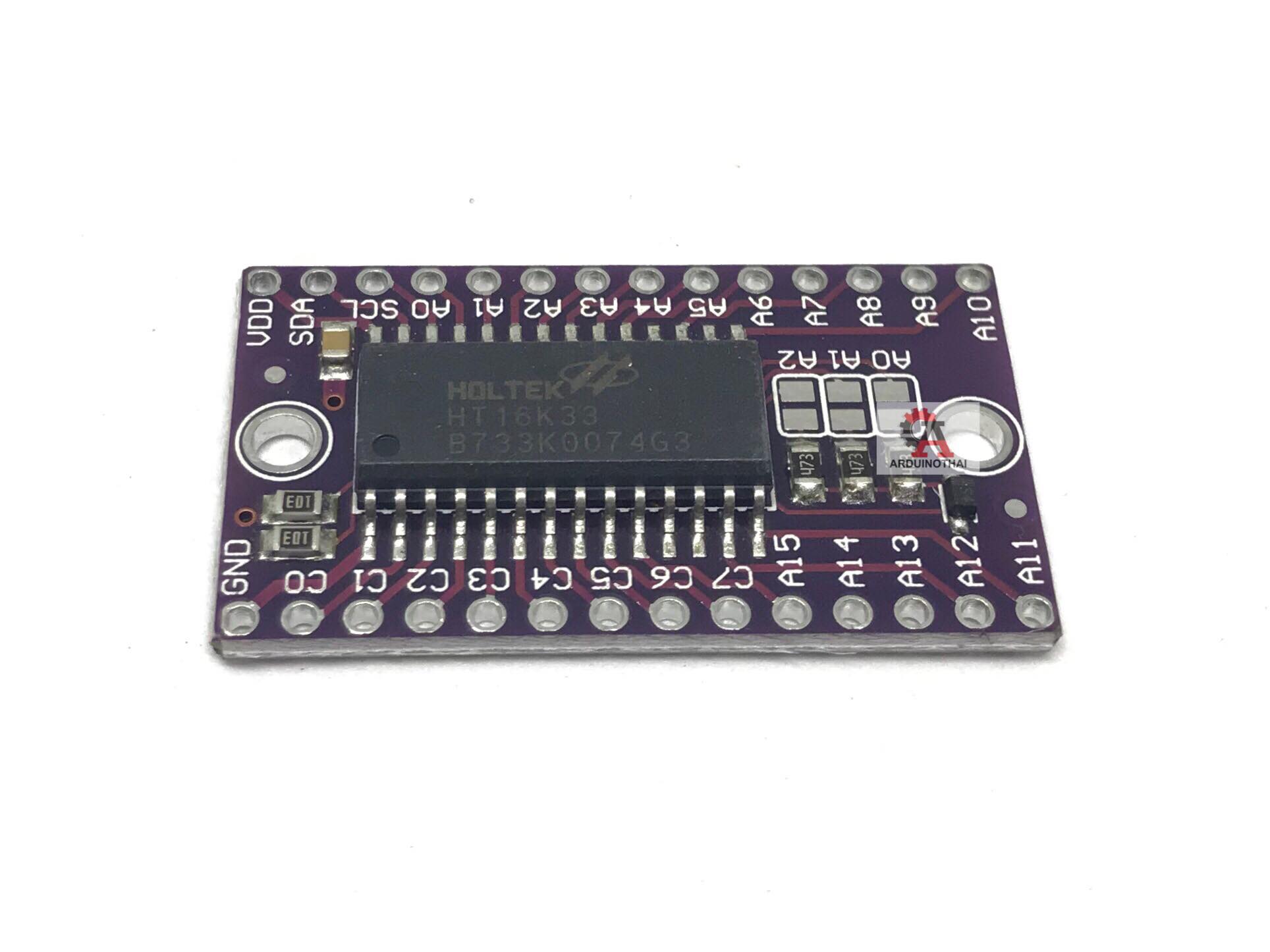
The module uses the 28-pin HT16K33 LED controller / driver chip from Holtek.
The HT16K33 is designed as a multi-functional device for driving a number of LED display applications including dot matrix, 7-segment and alphanumber 14-segment displays. It also includes a keyboard scanner by multiplexing the same pins for both driving the display and looking for key presses.
It can address up to 16 rows with 8 common pins, so can support up to 128 LEDs in a matrix or eight 7-segment or aphanumeric displays.
Communications with the chip is via I2C interface.
I2C Interface
The module has an easy to use I2C interface.
The default I2C address is 0x70. Address lines A0-A2 allow the address to be set to the range of 0x70 – 0x77 by solder bridging the pads to pull that pin high. Bridging all 3 pads results in the address 0x77.
The I2C lines have 10K pull-up resistors included on the module.
Module Connections
The board has two 14-pin male headers. The module brings the chip pins directly out to the corresponding header pin.
1 x 14 Header (left)
- GND = Vss / Ground
- C0 = COM0 / AD – Common output pin 0. Address source pin
- C1 = COM1 / KS0 – Common output pin 1. Key Source output 0
- C2 = COM2 / KS1 – Common output pin 2. Key Source output 1
- C3 = COM3 / KS2 – Common output pin 3. Key Source output 2
- C4 = COM4 – Common output pin 4.
- C5 = COM5 – Common output pin 5.
- C6 = COM6 – Common output pin 6.
- C7 = COM7 – Common output pin 7.
- A15 = ROW15 / K13 / INT – Row 15 driver. Key 13 input, Interrupt output
- A14 = ROW14 / K12 – Row 14 driver. Key 12 input
- A13 = ROW13 / K11 – Row 13 driver. Key 11 input
- A12 = ROW12 / K10 – Row 12 driver. Key 10 input
- A11 = ROW11 / K9 – Row 11 driver. Key 9 input
1 x 14 Header (right)
- VDD = Power (4.5V – 5.5V)
- SDA = I2C Data Input/Output
- SCL = I2C Clock
- A0 = ROW0 / A2 – Row 0 driver. Address bit 2
- A1 = ROW1 / A1 – Row 1 driver. Address bit 1
- A2 = ROW2 / A0 – Row 2 driver. Address bit 0
- A3 = ROW3 / K1 – Row 3 driver. Key 1 input
- A4 = ROW4 / K2 – Row 4 driver. Key 2 input
- A5 = ROW5 / K3 – Row 5 driver. Key 3 input
- A6 = ROW6 / K4 – Row 6 driver. Key 4 input
- A7 = ROW7 / K5 – Row 7 driver. Key 5 input
- A8 = ROW8 / K6 – Row 8 driver. Key 6 input
- A9 = ROW9 / K7 – Row 9 driver. Key 7 input
- A10 = ROW10 / K8 – Row 10 driver. Key 8 input
Assembling the Module
The module comes with 2 strips of male headers. These can be soldered on for use on a breadboard, or you can attach wires directly to the board depending on what your application requires.
When soldering the headers on, it is recommended to insert the headers into a solderless breadboard or perf board first to hold them in alignment while soldering.
OUR EVALUATION RESULTS:
These are useful modules for a number of LED display driver applications.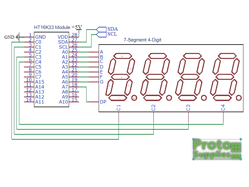
This is the same part that is used on a lot of the Adafruit LED display modules and so they have good library support for the device which is available through the Arduino IDE. The keyboard scanning function is not supported in their libraries.
The schematic for the example used is shown here.
Note that the common cathode connections for the LED module may be labeled as G1-G4, C1-C4 or other similar notation. When wiring things up, skip connecting to C2 on the HT16K33 module if using a module which does not have the clock colon as we are using here.
Connect A0 thru A6 to the LED segments A thru G respectively.
Connect C0, C1, C3 and C4 to the common cathodes of the LED. These may be labeled as G1-G4 or something similar. Note that we are skipping C2 which is used to drive the colon when using a clock style 7-segment module
Connect A7 to the LED DP (Decimal Point)
Connect SDA and SCL to each other between the MCU and HT16K33 module.
Connect VDD to 3.3V or 5V to match the MCU power and connect GND to ground.
วิธีการสั่งซื้อสินค้า
วิธีการชำระเงิน
ราคาสินค้าหน้าเว็บรวมภาษีแล้ว
ค่าจัดส่งสินค้า ยอดสั่งซื้อต่ำกว่า 1000 บาท ค่าจัดส่งทาง EMS 50 บาท
ยอดสั่งซื้อ 1500 บาทขึ้นไป จัดส่งให้ฟรีทาง Kerry
(ไม่รวมสินค้าหมวดหมู่DIY)
หลังจากสั่งซื้อและชำระเงินแล้ว จะต้องแจ้งชำระเงินทางหน้าเว็บเท่านั้น หากไม่มีการแจ้งชำระเงินภายใน 72 ชม. ระบบจะยกเลิกคำสั่งซื้อโดยอัตโนมัติ หากท่านยังต้องการสั่งซื้อสินค้าอยู่ จะต้องทำการสั่งซื้อใหม่อีกครั้ง
รายการที่แจ้งชำระเงินก่อนเวลา 15:00น. จะทำการจัดส่งในวันทำการเดียวกัน รายการที่แจ้งชำระเงินหลัง 15:00น. จะจัดส่งในวันทำการถัดไป จะทำการจัดส่งทุกวัน จันทร์-ศุกร์
***เฉพาะบริการจัดส่งKerryแจ้งยอดชำระก่อนเวลา10:30น. จะจัดส่งในวันทำการเดียวกัน
Kerryจัดส่งวันจันทร์-ศุกร์เท่านั้น
*เฉพาะวันเสาร์ รายการที่แจ้งชำระเงินก่อนเวลา 10:00น. จะทำการจัดส่งในวันทำการเดียวกัน รายการที่แจ้งชำระเงินหลัง 10:00น. จะจัดส่งในวันทำการถัดไป
หลังจากชำระเงินแล้ว คลิ๊กที่นี่ เพิ่อแจ้งชำระเงินทันที หากไม่สะดวกในการแนบหลักฐานการโอนเงิน กรุณาแจ้งชื่อธนาคาร และเวลาโอนเงินที่ถูกต้อง หากไม่สะดวกในการเข้าหน้าเว็บจริงๆ สามารถส่งหลักฐานการโอนเงินมาได้ทาง Official Line ID : @analogread

2.ชำระเงินผ่าน QR-CODE ฟรีค่าธรรมเนียม ทุกกรณี
...เลือกธนาคารที่แจ้งชำระเงินเป็น >>>>>>พร้อมเพย์<<<<<< หากมีค่าธรรมเนียมเกิดขึ้นทางเราจะใส่กลับคืนไปในกล่องพร้อมกับสินค้า

1. ชำระเงินผ่านร้านค้าโดยตรง
เลือกช่องทางที่คุณสะดวก เพื่อชำระเงินให้ร้านค้าโดยตรง หากมีข้อสงสัย กรุณา ติดต่อเรา

- ค่าธรรมเนียม 3.9% + 11 THB
- การชำระผ่าน PayPal คุณไม่จำเป็นต้องแจ้งชำระเงิน เนื่องจากระบบจะจัดการให้คุณทันที ที่คุณชำระเงินเสร็จสมบูรณ์
2. ชำระเงินออนไลน์ผ่าน 
เลือกช่องทางที่คุณสะดวก เมื่อชำระเงินเรียบร้อย คุณจะได้รับอีเมลยืนยันการชำระเงินทุกครั้ง (LnwPay ไม่มีค่าธรรมเนียมเพิ่มเติม อ่านรายละเอียด)


หมายเหตุ: สำหรับการชำระด้วยบัตรเดบิต (Debit Card) จำเป็นต้องสมัครใช้บริการจากธนาคารก่อนชำระเงิน ดูวิธีสมัคร ธ.กสิกร | ธ.กรุงเทพ | ธ.กรุงไทย


นโยบายการเปลี่ยนหรือคืนสินค้า
เช็คสถานะสินค้า


ระบบสมาชิก
